

Fitting a Frigomatic Keel Cooled Fridge System
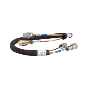
The Frigoboat Keel Cooler
The Keel cooler uses the water on the outside of the hull to cool and condense the refrigerant.
- Produced in marine bronze the sintered plate protects the heat exchanger from damage
- Sintered bronze is porous so the water passes through to the heat exchanger inside
- The heat exchanger is manufactured from cupro-nickel for maximum resistance against sea water corrosion.
- Supplied with sacrificial zinc anodes as standard for further protection from galvanic corrosion.
Technical Information:
- Dimensions 175 W 22 H 70 D (mm)
- Weight 2 (kg)
For full details see the full range of keelcoolers
Through the action of the compressor, the hot, high pressure refrigerant gas is circulated through the keel cooler where it is cooled & condensed into a pressurised liquid that is then fed to the evaporator (in the insulated box). In the Evaporator plate it is allowed to expand & evaporates (boils) at a very low temperature before being pulled back to the compressor as a low-pressure gas, where the cycle begins again.
Installation of the Frigomatic Keel Cooler
This must be mounted through the hull, below the waterline, by drilling a (38mm) hole (a 1.5″ hole may be used, carefully enlarging it, if necessary). Special constraints and working practices apply when installing the keel cooler on a vessel with a cored, metal, or carbon fibre hull. For these applications we suggest you consult a marine professional.
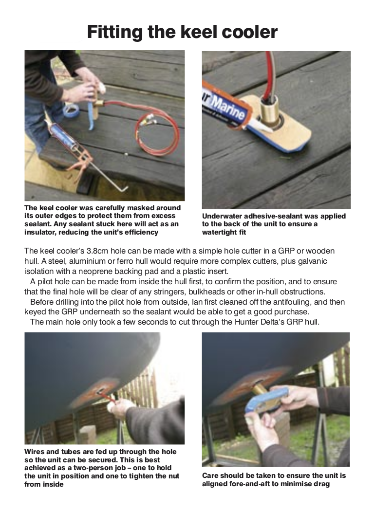
Recommended Fitting Instructions
1. Decide where the keelcooler is going to be positioned.
2. Drill a pilot hole where the keel cooler is to be located – from the inside out to avoid hitting any stringers etc.
3. For boats with double skins, if when drilling, there is a clear gap between the inner moulding and the hull, use a 4″ hole saw to cut away a large enough section of the inner moulding to fit the keel cooler directly to the outer laminate. If there is no gap between the inner moulding and the hull and the two are completely bonded together drill straight through both laminates with a 38mm hole saw.
4. Scrape away any existing antifouling so you are back to the bare hull to bond to.
Then drill a slightly over sized hole (38-40mm) so the keel cooler will easily slide up through. (it is a good idea to do a dummy run on a piece of wood to confirm).
5. Once you have done your test, drill the hole in the hull, fit the O ring and insert the keelcooler from the outside.
6. To hold it in place wind the nut on a couple of turns of the thread, so the washer holds it hanging down from the hull.
7. Mask the keelcooler so just the surface to be bonded to the hull is exposed.
8. Pull the O ring up and fill the recess with your waterproof adhesive
9. Then drop the O ring onto the adhesive and add more adhesive on top of the O ring and the rest of the top surface of the keelcooler.
10. Then with someone on the outside to hold the keelcooler in the correct orientation, push the keelcooler up flush to the hull and tighten the nut inside.
11. Once in place just a ‘good nip’ with the spanner will hold it all in place until the adhesive has gone off and the keelcooler will then be bonded in place.
Grounding and cleaning the Keel Cooler:
Provision is provided for a grounding/bonding wire to be attached. It is very important that the Keel Cooler is electrically connected to the battery negative, with no switch in the circuit between the Keel Cooler connection and the battery negative.
If the Keel Cooler being installed is the type without zincs, it must also be connected to the vessel’s bonding system and a sacrificial zinc anode. This is an important safety precaution and a connection must be made to the battery negative whether the keel cooler has zincs or not.
The keel Cooler should not be painted and must be inspected periodically for corrosion. Clean occasionally with a brush, never with a metal scraper.
For details on the recommended grounding please see the Frigoboat Correct Bonding document
Location and Installation of the Compressor:
The compressor unit must be mounted within 1.5m of the keel cooler – this dimension cannot be extended. It must be mounted on a horizontal surface in an area where it will not be susceptible to physical or water damage, it does not need to be ventilated but should be accessible for service.
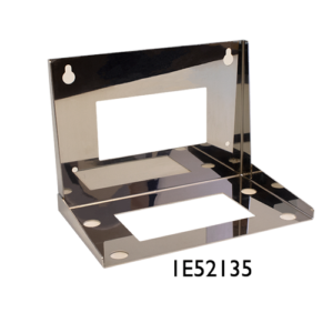
An anti-vibration mounting kit is supplied with the compressor that includes rubber mounts and steel inserts. The compressor must be mounted horizontally may be either screwed or bolted down using the supplied white, plastic washers. Alternatively, a Bulkhead Bracket can be used, in which case remove the stainless steel mounts from the compressor locating the unit to the bracket using the Teflon feet.
Installation of the Evaporator Plate
The evaporator has approximately 2.8m of copper tubing attached, with dust-plugs in the end fittings that must remain installed until the very last moment when the connections are ready to be made. A 30mm needs be drilled in the wall of the icebox. Carefully unroll the copper tubing, feeding it through to the area where the compressor & keelcooler is located. Some evaporators have sections of aluminium tubing close to the body of the evaporator that must be handled very carefully. Warnings to that effect are attached to the evaporator.
If the plate needs bending Penguin will do this for you if you supply a dimensioned drawing. See plate bending template doc The section of insulation that is free to slide on the tubing should be positioned starting at the point where the tubing exits the icebox. Do not add more insulation to the tubing.
Once the evaporator is installed, the exit hole in the box must be sealed with expanding foam, refrigeration putty, or other suitable material. Make sure that any drains are plugged and that there are no other holes or gaps through which air can enter the box. Any excess tubing may be carefully rolled up and fastened out of the way.
If the tubing is too short to reach the compressor / condensing unit, pre-charged extension pipe can be added between the evaporator and the compressor. There are 6 sizes available from 1m to 6m in length.